Home › Unlabelled ›
Water Cooled Chiller Schematic Diagram : Circuit Schematic For Water Cooled Liquid Chillers To 3 Tons : A thermostat to control the temperature of the coolant
Water Cooled Chiller Schematic Diagram : Circuit Schematic For Water Cooled Liquid Chillers To 3 Tons : A thermostat to control the temperature of the coolant. Many modern motorcycles still use air cooling, but for the most part, automobiles and trucks use liquid cooled systems and that is what this article will concentrate on. We also have repair guides for your vehicle, simply follow the link below and enter your vehicle's year, make, model, and engine to find the info you need to do the job right. The two in the top right and the one in the bottom right are all air cooled chillers and the rest are water cooled. The half closed cooling system is designed to circulate cooling water through the block only. Cooling system diagrams select model year:
Here is a picture gallery about water cooled chiller schematic diagram complete with the description of the image, please find the image you need. As a sort of integrated equipment, it no needs cooling tower, cooling water pump, boiler and corresponding Cooling system diagrams select model year: The process fluid absorbs heat from what is being cooled and then goes through the chiller where the heat is removed from the fluid and transferred to the ambient air. So we attempted to find some great air cooled chiller schematic.
The Basics Of Chillers Hvac Investigators from www.hvacinvestigators.com Chilled water schematic examples different chiller representations. The starting point for a loop always starts with your reservoir. Industrial water or glycol chiller systems contain two main circuits: We're talking about physics, thermodynamics, all sorts of fun stuff. The water pump is the central pump in your cooling system that injects coolant mix directly into the intake manifold and into your engine. Here is a picture gallery about water cooled chiller schematic diagram complete with the description of the image, please find the image you need. Water blocks are used to transfer heat from the source into the liquid that flows through the water block. A water pump to circulate the coolant;
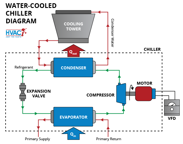
The cooling water flows inside the tubes and the exhaust steam condenses on the outside surfaces of the tubes.
Many modern motorcycles still use air cooling, but for the most part, automobiles and trucks use liquid cooled systems and that is what this article will concentrate on. Compressor (#1) the compressor has two functions in the refrigerant cycle. Video explanation and diagram of how liquid cooling works, as well as a list of what parts you need to build a water cooled pc.0:00 how liquid cooling works1. Micro fins that increase the cooling surface and channel design make the water block a crucial part of the loop that will enable you to achieve the highest overclocks! We're talking about physics, thermodynamics, all sorts of fun stuff. It's often explained as lego for adults. but managing the air cooling system within a pc is considerably more complex. The water pump is the central pump in your cooling system that injects coolant mix directly into the intake manifold and into your engine. Chilled water schematic examples different chiller representations. Cooling system diagrams select model year: A thermostat to control the temperature of the coolant I suggest you google fresh water cooling diagram for your particular when the thermostat is open the valve closes and the water flows.nov 09, · the flow diagrams shown are different from mine as they show two hoses from the intake (raw water) one leading to the stat and one going to the pump for the exhaust maniflods, where mine on the. Download chilled water system drawings with this chilled water plant drawings you will make your designs, just copy and paste it in your autocad and start connecting the chille dwater pipes from chiilers, cooling towers, fcu, ahu,.etc. Passages inside the engine block and heads;
We're talking about physics, thermodynamics, all sorts of fun stuff. The half closed cooling system is designed to circulate cooling water through the block only. Also keep in mind crossflow versus vertical flow in your search. Download chilled water system drawings with this chilled water plant drawings you will make your designs, just copy and paste it in your autocad and start connecting the chille dwater pipes from chiilers, cooling towers, fcu, ahu,.etc. These pulleys are located next to your water pump, connected to the water pump housing.
Schematic Of A Typical Chilled Water System Download Scientific Diagram from www.researchgate.net All 2016 2015 2014 2013 2012 2011 2010 2009 2008 2007 2006 2005 2004 2003 2002 2001 2000 1999 1998 1997 1996 1995 1994 1993 1992 1991 1990 1989 1988 1987 1986 1985 1984 1983 1982 1981 1980 1979 1978 1977 1976 1975 1974 1973 1972 1971 First, it removes the refrigerant vapor from the evaporator and reduces the pressure in the evaporator to a point where the desired evaporating temperature can be maintained. We also have repair guides for your vehicle, simply follow the link below and enter your vehicle's year, make, model, and engine to find the info you need to do the job right. As shown in the diagram below, raw water is picked up through the drive pickup or through a hull mounted pickup, if present it will pass through a sea strainer to clean debris out of the water. From there it will pass through the raw water pump. So, i made a post describing the best possible flow to include a processor and video card. The starting point for a loop always starts with your reservoir. Water blocks are used to transfer heat from the source into the liquid that flows through the water block.
This is only for a single video card, and not intended for an sli or crossfire setup.
So, i made a post describing the best possible flow to include a processor and video card. Cooling system diagrams select model year: But there are a few basic principles you can apply to almost any build to get optimal. I suggest you google fresh water cooling diagram for your particular when the thermostat is open the valve closes and the water flows.nov 09, · the flow diagrams shown are different from mine as they show two hoses from the intake (raw water) one leading to the stat and one going to the pump for the exhaust maniflods, where mine on the. Evaporative cooling is the process where warm water from an industrial process is pumped up to the top of the cooling tower where the water distribution system is. Micro fins that increase the cooling surface and channel design make the water block a crucial part of the loop that will enable you to achieve the highest overclocks! These pulleys are located next to your water pump, connected to the water pump housing. Chilled water schematic examples different chiller representations. It's often explained as lego for adults. but managing the air cooling system within a pc is considerably more complex. A refrigeration circuit and a fluid circuit. The cooling system is made up of: Browse the excerpts below to find out how to access automotive repair guides through autozone rewards. Download chilled water system drawings with this chilled water plant drawings you will make your designs, just copy and paste it in your autocad and start connecting the chille dwater pipes from chiilers, cooling towers, fcu, ahu,.etc.
We're talking about physics, thermodynamics, all sorts of fun stuff. Animated schematic to 30 tons. Evaporative cooling is the process where warm water from an industrial process is pumped up to the top of the cooling tower where the water distribution system is. A refrigeration circuit and a fluid circuit. But there are a few basic principles you can apply to almost any build to get optimal.
Diagram York Chiller Diagram Full Quality Tablexpogroup Victortupelo Nl from mydax.com Here is a picture gallery about water cooled chiller schematic diagram complete with the description of the image, please find the image you need. The water pump is powered by the accessory belt of your engine, which circulates on the water belt pulley. Passages inside the engine block and heads; The heat is transferred from the cpu into a cooling block. the cooling block is simply a hollow heat sink with both an inlet and outlet for the. I'll show you some examples of how chillers are illustrated in schematics as it really varies. The flow diagrams shown are different from mine as they show two hoses from the intake (raw water) one leading to the stat and one going to the pump for the exhaust maniflods, where mine on the 318 only has the one raw water inlet which divides at the stat housing for the exhaust manifolds and the engine. A refrigeration circuit and a fluid circuit. The cooling water flows inside the tubes and the exhaust steam condenses on the outside surfaces of the tubes.
Truly, we have been remarked that air cooled chiller schematic diagram is being one of the most popular field at this time.
When reaching for cooling capacity, look at width and thickness, taking care not to choose a radiator that's too wide for the radiator support. From there it will pass through the raw water pump. A thermostat to control the temperature of the coolant The chilled water will enter the ahu's/fcu's at around 6°c (42.8°f) and by the time it leaves the heat exchanger within the ahu/fcu it will have risen to around 12°c (53.6°f) and will then make its way back to the air cooled chiller to dump this heat into the atmosphere before repeating the cycle. I'll show you some examples of how chillers are illustrated in schematics as it really varies. The two in the top right and the one in the bottom right are all air cooled chillers and the rest are water cooled. The cooling system is made up of: But there are a few basic principles you can apply to almost any build to get optimal. Industrial water or glycol chiller systems contain two main circuits: So, i made a post describing the best possible flow to include a processor and video card. Building a modern desktop pc is surprisingly easy, thanks to modular parts and a lot of solid engineering. Passages inside the engine block and heads; The water then gets distributed by cooling tower nozzles to the wet deck.