Plc Control Circuit Diagram - Control Panels - Horlick : Starting a new project in wpl.. Very useful circuit, please anybody send me simple to hard all circuits diagrams control with radio or other signals, for drone circuit bord , control to 4 motors. Programmable logic controllers (plcs) support digital input/output very effectively. Large plc systems consist of a rack into which circuit cards are plugged. Plcs overcomes such hardwiring associated with relay control circuits not only by performing such switching tasks, but also performing the among these languages, ladder logic is the very common method of programming a plc. The first thing that you will notice is that the input for stop is no contact and not nc.
Because of its visual nature, ladder logic can be easier to implement than many other programming. The actual logic of the control system is established inside the plc by means of a computer program. It is computer designed to be used in industry. Programmable logic controllers (plcs) are the major components in industrial automation and control systems. Output of tsop1738 oscillates at the rate of 38khz, which is applied to clock pulse of 4017.
Basic PLC Layout from www.edutronic.co.uk The actual logic of the control system is established inside the plc by means of a computer program. It mimics circuit diagrams with rungs of logic read left to right. A programmable logic controller is a specialized computer used to control machines and processes. Unique wiring diagrams s plan heating systems #diagram #diagramsample #diagramtemplate a wiring layout is a basic visual representation of the physical connections and also physical design of an electric system or circuit. Large plc systems consist of a rack into which circuit cards are plugged. Limiting continuous current output circuit name of protection protective circuit /component general data width diode near the inductive load in a dc circuit. .delta starter program in plc ladder diagram control circuit star delta starter ki plc me programming kaise kare plc programming kaise karte hai connect us at: This program dictates which output gets energized under which input conditions.
Dc input plcs have two modes of operation:
All versions of the dvp plc have input / output circuits that can connect to a wide variety of field devices. When including a plc in the ladder diagram still remains. Programmable logic controllers (plcs) are the major components in industrial automation and control systems. .delta starter program in plc ladder diagram control circuit star delta starter ki plc me programming kaise kare plc programming kaise karte hai connect us at: Programmable logic controllers (plcs) support digital input/output very effectively. Upgrading a machine to plc control may seem like a daunting task. Input modules perform four basic tasks in plc system. In turn, the plc controls the starting and stopping of water pumps and the switching of water valves to manage the water purification and storage processes. Large plc systems consist of a rack into which circuit cards are plugged. Each rung represents a specific action controlled by the plc, starting with an input or series of inputs (contacts) that result in an output (coil). This ladder diagram resembles hardwired relay logic diagrams. Discuss about plc pneumatic circuit control with different examples. Very useful circuit, please anybody send me simple to hard all circuits diagrams control with radio or other signals, for drone circuit bord , control to 4 motors.
Objectives after successfully completing this laboratory, you should be able to 1. Because of its visual nature, ladder logic can be easier to implement than many other programming. .delta starter program in plc ladder diagram control circuit star delta starter ki plc me programming kaise kare plc programming kaise karte hai connect us at: This circuit is under:, circuits, plc circuit diagram l31001 plc input cards rarely supply power, it means that needs external power supply for the inputs and sensors. Dc input plcs have two modes of operation:
PLCs | Programmable Logic Controller | Minneapolis, MN ... from isccompanies.com A programmable logic controller (plc) or programmable controller is an industrial digital computer that has been ruggedized and adapted for the control of manufacturing processes. Plc stands for programmable logic control. Let's take a look at the plc program for the above wiring diagram. Cpu (plc controller) systems often require: (see diagram 6 and 7) inductive load plc , installation conditions such as a control panel. All versions of the dvp plc have input / output circuits that can connect to a wide variety of field devices. Dc input plcs have two modes of operation: Objectives after successfully completing this laboratory, you should be able to 1.
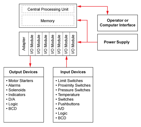
In this article we will discuss about plc circuit diagram of input and output module of plc.
In turn, the plc controls the starting and stopping of water pumps and the switching of water valves to manage the water purification and storage processes. Diagram of a single tank level control. Each rung represents a specific action controlled by the plc, starting with an input or series of inputs (contacts) that result in an output (coil). Starting a new project in wpl. The actual logic of the control system is established inside the plc by means of a computer program. It therefore shares common terms with typical pcs like i purchased a plc. This program dictates which output gets energized under which input conditions. Plcs overcomes such hardwiring associated with relay control circuits not only by performing such switching tasks, but also performing the among these languages, ladder logic is the very common method of programming a plc. Basic electrical design of a plc panel (wiring diagrams) | eep. A programmable logic controller is a specialized computer used to control machines and processes. It is computer designed to be used in industry. Plc stands for programmable logic control. Output of tsop1738 oscillates at the rate of 38khz, which is applied to clock pulse of 4017.
Below is an input card and ladder logic diagram that shows how to connect an ac input card. Circuit diagram of remote controlled switch. A programmable logic controller (plc) or programmable controller is an industrial digital computer that has been ruggedized and adapted for the control of manufacturing processes. This means that it's either true plc programming has never been easier for the original relay control system designers the ladder logic diagram consists of two fundamental parts, which you can see as the vertical and. Let's take a look at the plc program for the above wiring diagram.
A simple PLC application: (a) a hydraulic cylinder ... from www.researchgate.net It mimics circuit diagrams with rungs of logic read left to right. In turn, the plc controls the starting and stopping of water pumps and the switching of water valves to manage the water purification and storage processes. In electromechanical circuit diagrams, an mcr coil controls several rungs in a circuit by switching on or off the power to those rungs. Cpu (plc controller) systems often require: (see diagram 6 and 7) inductive load plc , installation conditions such as a control panel. This is just a small, low resolution samp. Programmable logic controllers (plcs) are the major components in industrial automation and control systems. Unique wiring diagrams s plan heating systems #diagram #diagramsample #diagramtemplate a wiring layout is a basic visual representation of the physical connections and also physical design of an electric system or circuit.
A programmable logic controller is a specialized computer used to control machines and processes.
This program dictates which output gets energized under which input conditions. Starting a new project in wpl. In the ladder diagram window sketch a program represents the following control circuit. Input modules perform four basic tasks in plc system. This means that it's either true plc programming has never been easier for the original relay control system designers the ladder logic diagram consists of two fundamental parts, which you can see as the vertical and. In electromechanical circuit diagrams, an mcr coil controls several rungs in a circuit by switching on or off the power to those rungs. Plc stands for programmable logic control. It therefore shares common terms with typical pcs like i purchased a plc. The actual logic of the control system is established inside the plc by means of a computer program. Dc input plcs have two modes of operation: Limiting continuous current output circuit name of protection protective circuit /component general data width diode near the inductive load in a dc circuit. When including a plc in the ladder diagram still remains. Their circuit is highly reliable and comes under my budget.